Boost Converter Efficiency Measure
Prototype MPPT system has been developed for Buck-Boost converter using the above described methods and tested experimentally. The efficiency can be calculated as below wihout the loss caused by driver and controller a Pin VinIinaverage.

For Buck Boost Converter A Duty Ratio B Inductor Current C Download Scientific Diagram
I measured average current flowing through the inductor and output voltage.
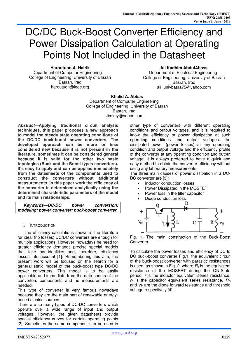
Boost converter efficiency measure. A capacitor inductor or the two in combination. To calculate the power losses and efficiency of DC to DC buck-boost converter Fig1 the. I am trying to measure the efficiency of a DCDC boost-converter in several operating points as precisely as possible.
The latest addition to this lineup is the LTC3532 a 300mA buck-boost converter which incorporates automatic Burst Mode operation adjustable switching frequency and. I think the four multimeters are pretty high quality Flukes. This calculation gives a more realistic duty cycle than just the equation without the efficiency factor.
In particular in the converter topologies like buck boost flyback. This test usually takes place at the nominal input voltage and with the output load set to nominal or maximum specified ratings. Comparing actual measurements of an optimised circuit with the theor.
If you consider ideal situation that both the input and output voltages are pure dc then you can use dc. Measuring efficiency of buck-boost converter using with and without modified perturb and observe po mppt algorithm of photo-voltaic pv arrays Md. From that I calculated powers Pin and Pout.
Basic Synchronous Boost Converter. For circuits with a high output current generally starting above three amps and especially five amps or more replacing the output diode with a MOSFED makes a lot of sense both for efficiency and for heating. The boost is a DCDC so you just measure DC values.
This converter operates in either the CCM or the DCM over the entire load current range thus providing a more direct comparison with the developed higher-order model. I am getting the efficiency of approx. Since 48k Ohms is not a standard value of resistance you might start off by setting the boost converter to output 47 volts and use a 47k Ohm.
The efficiency of a boost converter at this special condition may be not found in the datasheet. A boost converter step-up converter is a DC-to-DC power converter that steps up voltage while stepping down current from its input supply to its output load. System loads operate at idle mode for most of the time which consume little energy.
Khaliluzzaman INTRODUCTIONSolar photovoltaic array PV is becoming an increasing attractive way to generate power around the. To remedy this the LM27313 standard asynchronous boost converter will be used to compare the calculated versus measured results of the efficiency estimations. Efficiency determines the internal power dissipated by the DCDC converter and how efficiently input power transfers to the converter output.
Either an estimated factor eg. Construct the converters without additional measurements. It is a class of switched-mode power supply SMPS containing at least two semiconductors a diode and a transistor and at least one energy storage element.
Reference 1 Leon Chen Power Loss Analysis for Synchronous Buck Converter Application Engineer Dept data 2013. A quick look at the input and output power for a simple one-inductor DC boost converter. Linear Technology offers a family of buck-boost converters capable of supplying from 200mA to 2A with excellent efficiency.
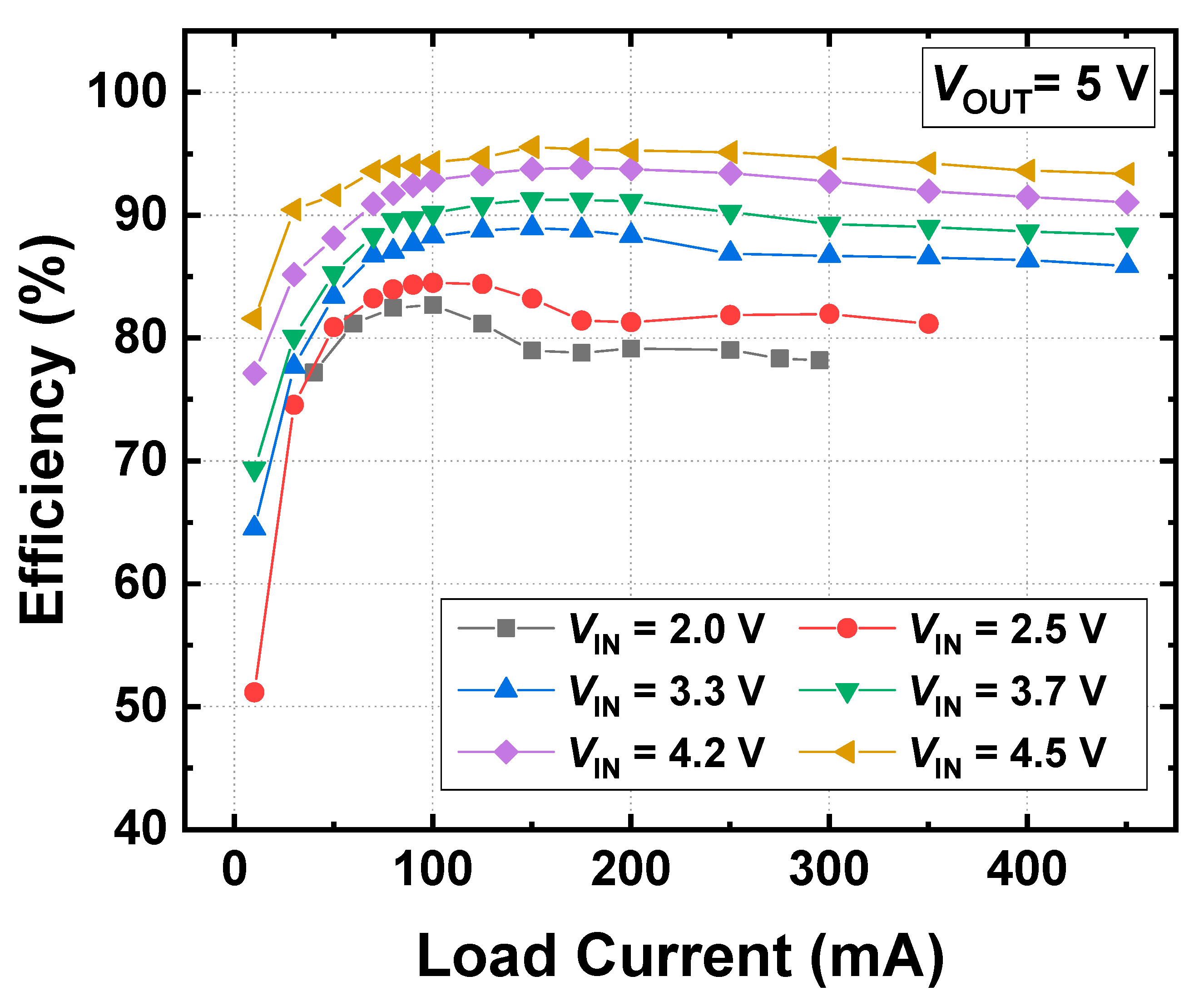
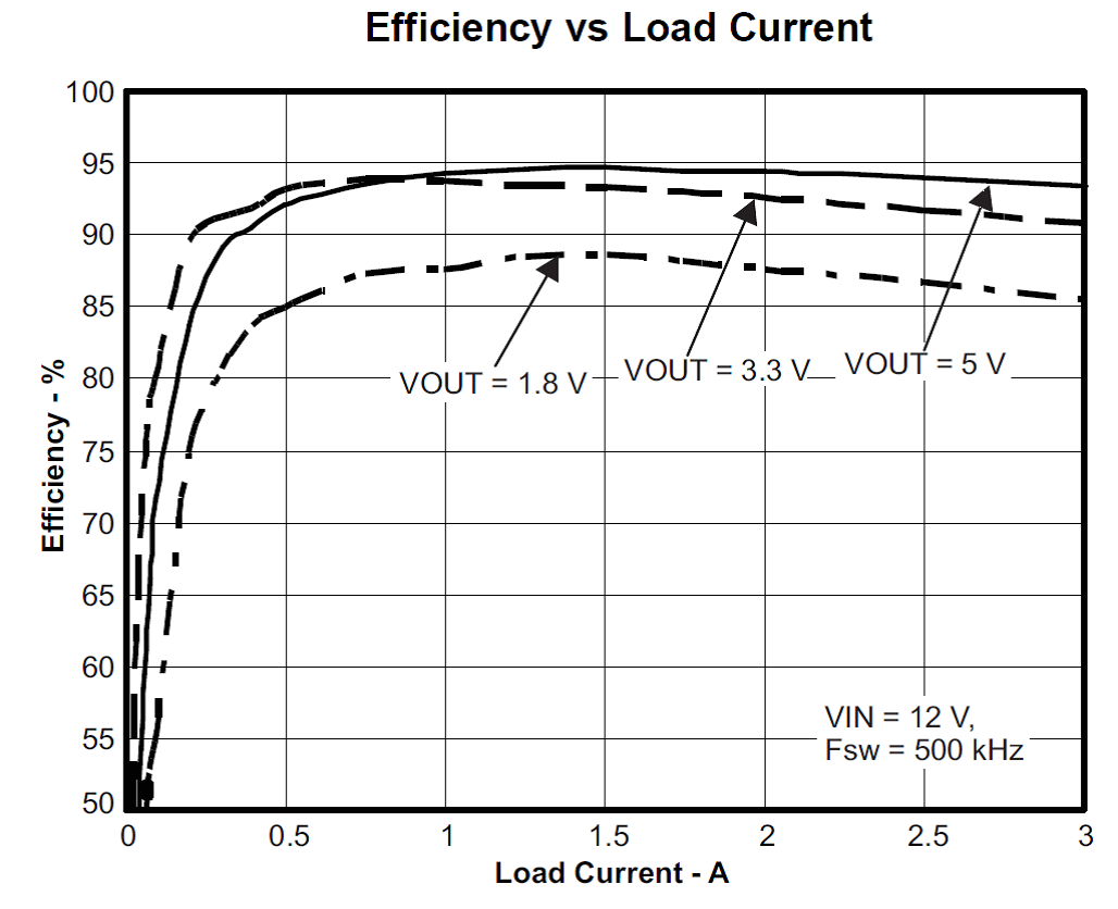
That would require 48k Ohms of resistance and would require a 12 Watt resistor rating. Start out with a load of 10mA or so. Specifically efficiency increases roughly by 1 percent at 300 kHz Fig.
How to measure efficiency of boost converter. 1 2 percent at 550 kHz Fig. These are the same levels that I recommend for switching from a non-synchronous buck to a synchronous buck.
I know that boost converters can be more efficient 90. 2 and up to 4 percent at 1 MHz Fig 3. The loss calculation also compares with real buck converter measurement and provides the key component loss data to consider how to improve the buck converter efficiency for component and PCB plane consideration.
So we need to calculate or measure the total input current of the boost converter also the output current of the battery at the idle mode to estimate the battery lifetime. The meter will display. So I need some suggestion about modifications in my circuit to improve the efficiency.
To get a precise value of the efciency of the ACDC converter it would be optimal to get physical access and. 80 which is not unrealistic for a boost converter worst case efficiency. The PV array which is to be used with this system giving a 50 W maximum power and an 216 V open circuit voltage at an irradiation of.
These are averages if you will. Estimated 80 The efficiency is added to the duty cycle calculation because the converter has to deliver also the energy dissipated. Click on Image to Enlarge.
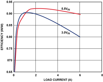
This result is especially notable since it is during heavy current loads that designs are most thermally challenged. A Typical Boost Converter A DC-DC boosting function is basically realized by first energizing an inductor in one cycle and releasing the stored energy to the output in the other as realized by the circuit shown in Figure 1a when switch MN is engaged MP and D are off and inductor L is energized connected from input supply V IN to ground and later when switches MP and D are on. In this paper work the efficiency of.
Right now I am measuring my input-voltage and output-voltage with a multimeter and the input-current and output-current over a shunt-resistor with a multimeter as well. The internal charger in an EV is a power converter containing a rectier and a boost converter to change the 230 V AC to DC with the same voltage level as the MAIN which typically is 250 400 V. efficiency of the converter eg.

Boost Converter Losses A Conduction And Switching Losses B Download Scientific Diagram
Synchronous Inverse Sepic Topology Provides High Efficiency Buck Boost Voltage Converters Analog Devices

Designing A Flyback Converter With The Max17291 Micropower Boost Converter Ic
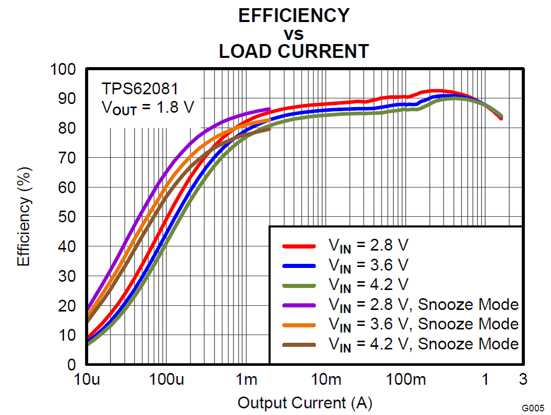
Boost Converter Has High Efficiency At Light Loads
Electronics Free Full Text Delta Sigma Modulator Based Step Up Dc Dc Converter With Dynamic Output Voltage Scaling Html

A Modified High Step Up Non Isolated Dc Dc Converter For Pv Application Journal Of Applied Research And Technology Jart
Pdf Dc Dc Buck Boost Converter Efficiency And Power Dissipation Calculation At Operating Points Not Included In The Datasheet

A Modified High Step Up Non Isolated Dc Dc Converter For Pv Application Journal Of Applied Research And Technology Jart
Using A Dc Dc Converter To Power An Adc Power Management Technical Articles Ti E2e Support Forums

High Efficiencies At Light Loads A Voltage Boost Converter From Texas Instruments News
![]()
Pdf Dynamic Duty Cycle Limitation Of The Boost Dc Dc Converter Allowing Maximal Output Power Operations

Measured Efficiency Curves Of The Buck Converter Download Scientific Diagram

A Modified High Step Up Non Isolated Dc Dc Converter For Pv Application Journal Of Applied Research And Technology Jart
![]()
Monitoring Instantaneous Power Of A Dc To Dc Converter Using A Dynamic Daq Keysight Blogs
Using A Dc Dc Converter To Power An Adc Power Management Technical Articles Ti E2e Support Forums

Boost Converter Efficiency Through Accurate Calculations Power Electronics
A Modified High Step Up Non Isolated Dc Dc Converter For Pv Application

Bode Plot Of Boost Converter Download Scientific Diagram

Boost Converter Has High Efficiency At Light Loads
Posting Komentar untuk "Boost Converter Efficiency Measure"