Boost Converter Efficiency Equation
If in addition to the transistor on resistance itexR_ONitex the converter diode has a voltage drop itexV_D_0itex symbolically derive an expression for the efficiency of the converter where 100 POPIN. 80 which is not unrealistic for a boost converter worst case efficiency.
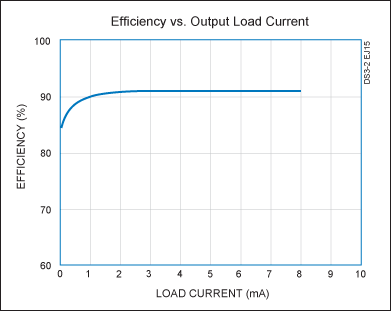
Boost Converter Has High Efficiency At Light Loads
Estimated 85 15 VINmin minimum input voltage D duty cycle calculated in Equation 14.
Boost converter efficiency equation. 0 0 rrLC P PP P 6 Replacing PO rL P rC by their respective expressions the conversion effi-cien cy becomes. Most boost converters average around 85 to 90 under medium load and up to 95 on heavy load. Rectangular pulses of voltage into an inductor result in a triangular current waveform.
P OUT P IN. For a DCDC converter the input and output powers are just the product of their respective currents and voltages. The equation can be rewritten.
The Greek symbol Eta is usually used to represent Efficiency Here is the formula for determining a power converters Efficiency . efficiency of the converter eg. The function of buck converter is to step down the input voltage.
Since 48k Ohms is not a standard value of resistance you might start off by setting the boost converter to output 47 volts and use a 47k Ohm resistor which IS a standard value. Where I Q is the quiescent current of the linear regulator when there is no load. The duty cycle limits can be calculated from the desired output voltage level and efficiency as shown below.
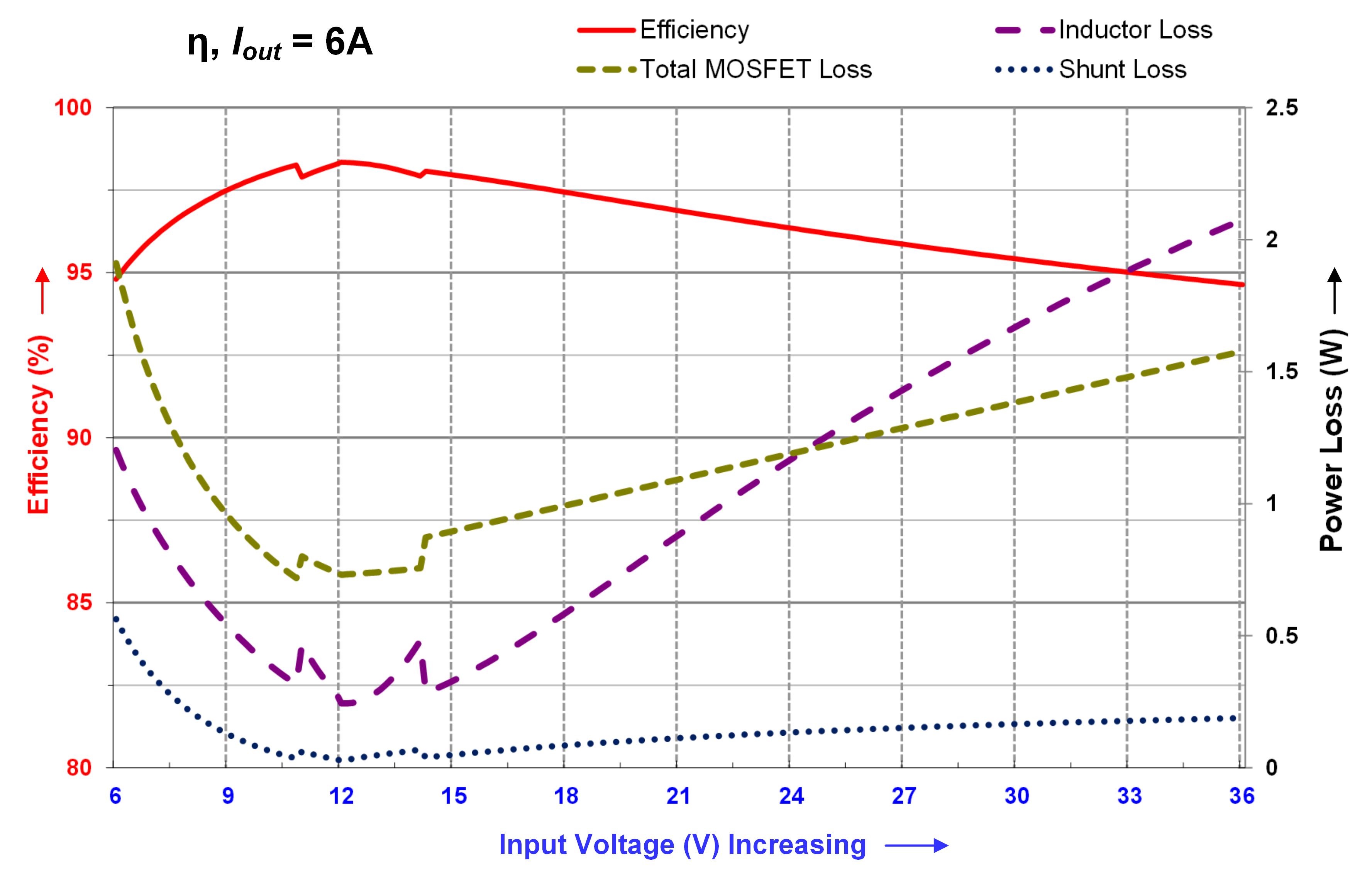
Again using a typical asynchronous boost converter the dc losses in the NFET switch the diode and the inductor are used to generate a power-balance equation given by P IN P SWITCH P DIODE P INDUCTOR P OUT. Buck converter boost converter buck-boost converter and flyback converter. So this provides a quick and easy method to calculate the efficiency of a buck-boost converter at different.
For synchronous bucks the voltage drop across the control MOSFED and the upward MOSFED rarely exceed 100 millivolts. 1IotVotdtIitVitdt and its related formula is. I know the voltage is related to the input voltage by V Vin1-D where D is the duty cycle.
5 Volts to 15 Volts by using a boost converter designed specifically for this task. From Ohms law P out V out x I out. This is the maximum on time of the boost converter.
The converter uses a transistor switch typically a MOSFET to pulse width modulate the voltage into an inductor. And what I prefer to do is estimate the power efficiency and then divide the ideal duty cycle equation by that efficiency. Pout Pin For example the efficiency of a converter that provides 500W of output power Pout and requires 625W for the input power Pin would be 80 500W625W080.
The function of buck-boost combines the functions of both buck converter and boost converter and can theoretically achieve any output. Boost converter with series losses through inductor and capacitor model 1. There are mainly four types dc-dc converters.
The conversion efficiency is defined by. The efficiency of a linear regulator is defined by the ratio of the delivered output power P OUT to the power consumption P IN. This calculation gives a more realistic duty cycle than just the equation without the efficiency factor.
You might be thinking how can he know the efficiency before building the converter. Results of simulation show that the switching converter will boost voltage from 5 volts to 15 volts with power conversion efficiency. The efficiency formula is.
Output current . The boost converter is a high efficiency step-up DCDC switching converter. Ideal model of the boost converter.
The function of boost converter on the other hand is to step up the input voltage. 2Iotdt Votdt Iitdt Vitdt There are two completly different equations or may be expression related formula is idiomatic and has other meaning from the one that I know English is my second language. I in I out I Q.
All aim calculations tests data and conclusions have been documented within this report. Designing a boost converter sounds complicated and intimidating. I have tested a boost converter under different duty cycles.
. V OUT I OUTV IN I OUT I Q. Then you could add another 47k Ohm resistor in parallel to the 1st one to get a 20mA load and another in parallel for a 30mA load etc.
The duty cycle will determine the maximum and minimum voltage levels that can be output from a typical boost converter. Estimated 80 The efficiency is added to the duty cycle calculation because the converter has to deliver also the energy dissipated. Shown in Equation 1.
Output voltage. 1 2 This equation highlights the biggest stumbling block when working with boost converters. We need to first to look at these two equations below 6.
Adding the triangular ripple current we arrive at Equation 2. But for some reason as I increase this duty cycle with my input voltage kept constant the power efficiency of the converter goes down. To calculate the DCDC buck-boost converter efficiency at any output voltage given that the power supplys efficiency is known at any other output voltage.
Duty cycle limits for asynchronous and synchronous boost converters. Consider a Buck-Boost converter. Either an estimated factor eg.
P in V in x I in. Efficiency Since the total power loss is obtained the efficiency can be calculated with the following equation.

Boost Converter Operation Download Scientific Diagram

What Is Boost Converter Circuit Diagram And Working Electronic Circuit Projects Circuit Diagram Circuit
Increase Dc Dc Converter Efficiency Understanding Operating Modes And Power Losses Power Management Technical Articles Ti E2e Support Forums

For Buck Boost Converter A Duty Ratio B Inductor Current C Download Scientific Diagram
Buck Boost Converter Analysis
Output Voltage Vs Duty Cycle Of The Boost Converter Circuit For Download Scientific Diagram

Buck Boost Converter What Is It Formula And Circuit Diagram Electrical4u
1 Ideal Boost Converter Circuit Download Scientific Diagram

Multi Level Boost Converter Download Scientific Diagram

Boost Converter And Its Steady State Waveforms A Boost Converter B Download Scientific Diagram

A Boost Converter Using A Ideal Switches B A Diode As The Download Scientific Diagram

The Dc Dc Boost Converter Power Supply Design Tutorial Section 5 1 Power Electronics News
Boost Converter Wikiwand

Pin On Electronic Circuit Diagrams

Boost Converter Design Circuit Download Scientific Diagram
Increase Dc Dc Converter Efficiency Understanding Operating Modes And Power Losses Power Management Technical Articles Ti E2e Support Forums

Parameter Comparison Of Boost Cascaded Boost Converter For 100 W Download Table

Boost Converter Efficiency Through Accurate Calculations Power Electronics

Boost Converter Operation Download Scientific Diagram
Posting Komentar untuk "Boost Converter Efficiency Equation"